hydraulic flow meter symbol
Flow Direction of Hydraulic Line Flexible. -envelope for long and short dashes around two or more component symbols.

A Guide To Common Hydraulic Symbols Engineeringclicks
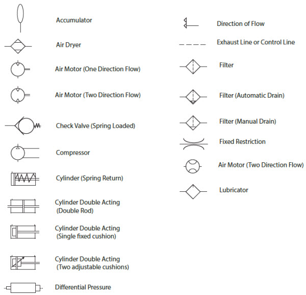
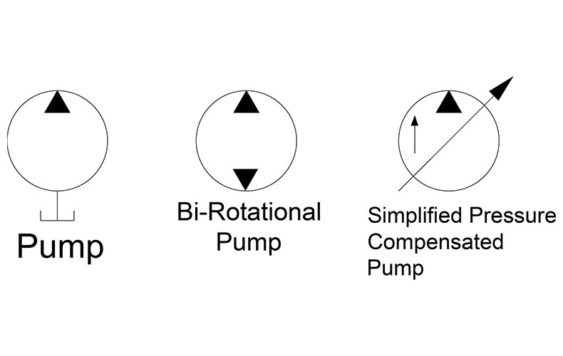
Simplified symbols are shown for commonly used components.
. Navys fluid power training course. PID PIP Sample Drawing. Print them off and use them for reference.
Composite symbols can be devised for any fluid power component by combining basic symbols. Identify if lines cross. The control lines are represented by a dotted line.
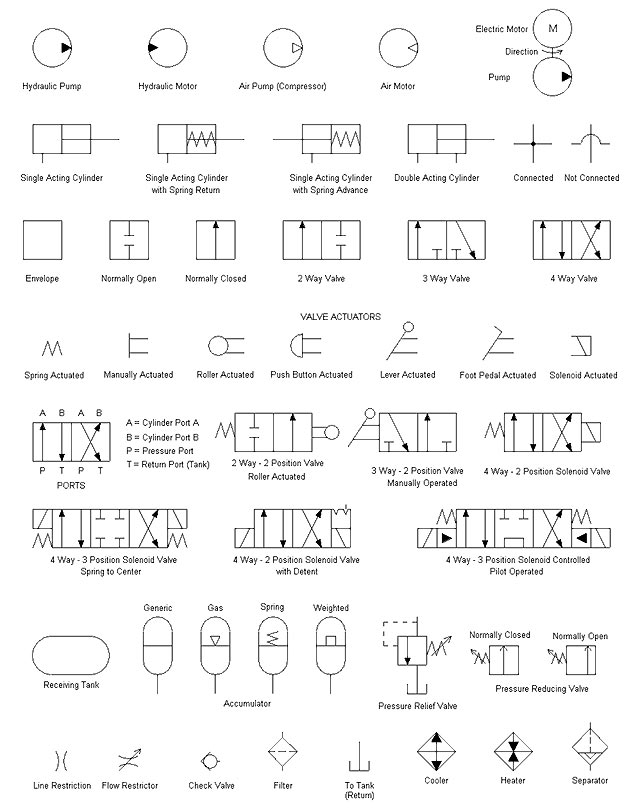
By understanding the symbols and following the flow path of the schematic success in determining a problem with your system becomes quicker and more rewarding. Select to place the reservoir below the filter. Valves Two Way Valves 2 Ported Valves.
Ivcrd2vcr adjustable 3-way flow control wr1tå reverse flow check cc. Hydraulic Symbol dialog box click Miscellaneous. Line Working Main Line Pilot For Control Line Enclosure Outline.
Click on the links below to get cheat sheets 5 and 6 of hydraulic symbols. I vcrt3vcr adjustable 3-way flow control flow divider spool type flow divider cc. IEC 60617 Sample Drawing.
Dc03 rotary flow divider cc. -dashed line for pilot drain. In the Insert Component.
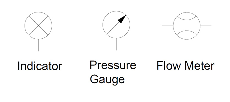
The following list is contains hydraulic schematic symbols to DIN ISO 1219. Direction of Flow - Hydraulic. Displayed Programmable Indicator symbol.
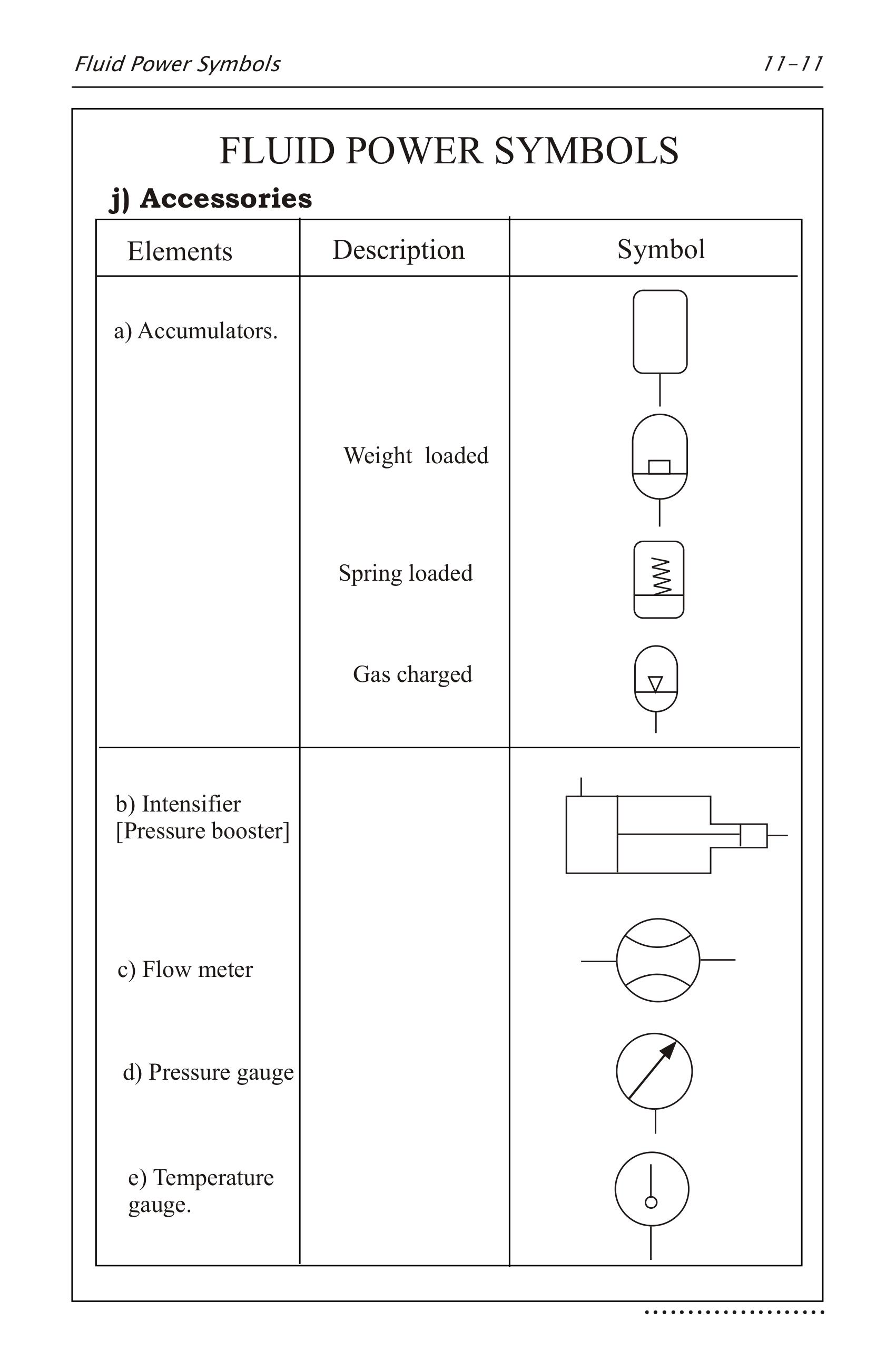
IEC 60617 Sample Drawing. 1216 This standard provides basic symbols which differentiate between hydraulic and. The complexity of these components are difficult to represent fully so a family of graphic symbols have been developed to represent fluid power components and systems on schematic drawings.
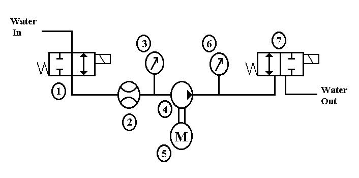
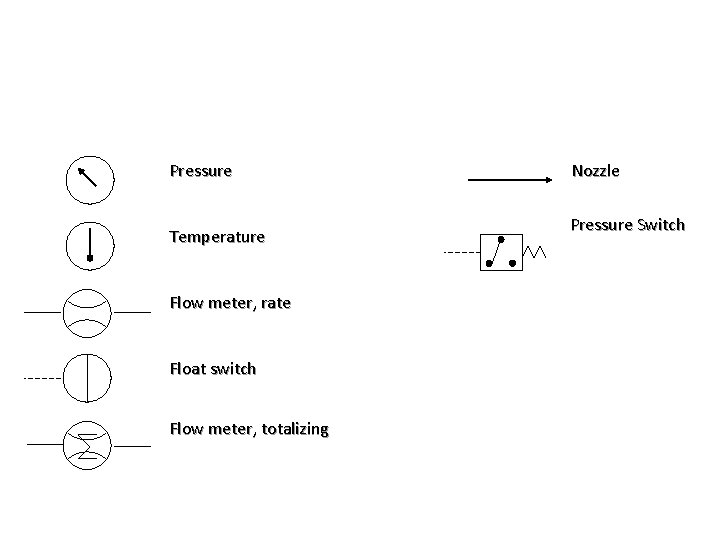
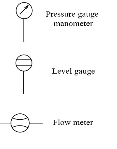
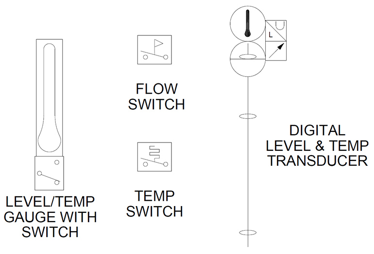
Miscellaneous hydraulic symbols and devices used in hydraulic circuit design. For different displays or electrical communication systems the flow meter symbol would remain the same but the symbol in the square connecting box would change. There are so many symbols to identify and lines to keep track of.
Quick Disconnect Without Checks Connected. The bottom symbol shows how to measure flow in both directions with a single flow meter. The direction of fluid flow is indicated by arrows if necessary.
The straight lines either side of the 3 way 2 position valve show that it uses a proportional spool eg. Respond to the prompts as follows. Ivcrt 3vcr adjustable 3way flow control flow divider eg.
Averaging pilot annubar target flow ultrasonic flow meter. Pipelines on hydraulic circuits are shown with lines connecting the elements. Miscellaneous dialog box click Reservoir.
Pid symbols for valves equipment instrumentation. Dcl9-9-9-9r lowering valve with reverse flow check ecvf throttle with reverse flow check egeg. The basic steps to reading a hydraulic schematic are.
This page provides the Appendix containing graphic symbols for fluid power diagrams from the US. I hope to impart to you a systematic approach to reading a hydraulic schematic. Flow Nozzle Meter symbol.
JIC NFPA Sample Drawing. As the spool moves over the internal orifice opens gradually rather than instantly as it would in. Thermal release hydraulic shut valve.
Click Schematic tab Insert Components panel Insert Hydraulic Components. Ivcrd 2vcr adjustable 3-way flow control with reverse flow check eg. This symbol shows a basic priority flow control valve which is designed to always provide flow to the main priority flow path up to a pre-set limit then supply the excess flow to the third line.
Spool type flow divider eg. Connecting Pressure Lines usually representing plastic tubing for pneumatic air lines with low pressures metal piping for hydraulic fluid lines with high pressure -continuous line for flow line. Dc03 rotary flow divider.
Diaphragm Meter symbol. JIC NFPA Sample Drawing. By reading a schematic and following its.
AC500 PLC COMM INT Modules. Water Flow Meter Self-Operating Release Valve TEMA TYPE BEM Spray Cooler Shell and Tube Heat 3 Reboiler. Flow indicator flow meter tachometer torque meter pressure switch micro switch adjustable 2-way flow control with reverse flow check eg.
Electro-Hydraulic Valve Spring Gate Valve Balanced Diaphragm Gate Valve Slide Valve Metering Coke Post Indicator. Hydraulic flow meter symbol. What symbols represent hydraulic components.
The ability to determine a point of entry for removal of components or installation of gauges and or flow meters becomes quicker. This list is designed as ad aid for creating symbols. Hydraulic circuits can be comprised of an infinite combination of cylinders motors valves pumps and other equipment connected via hydraulic pipes and tubes.
The symbol shows a fluid flow meter with digital display. Cheat sheets 5 and 6 are lists of hydraulic symbols like valve hydraulic symbol solenoid valve symbol directional valve symbol servo valve symbol electric motor symbol lubricator hydraulic symbol gauge hydraulic symbol indicator hydraulic symbol. Flow control wrrh reverse flow check cc.
PID PIP Sample Drawing. Hydraulic Reservoir - Open. Direction of Flow - Pneumatic.
Standard PID Symbols Legend Industry Standardized PID Symbols.

Hydraulic Circuit Schematic Showing The Location Of The Flow Meter Used Download Scientific Diagram
Pneumatic Circuit Symbols Explained Library Automationdirect

Common P Id Symbols Used In Developing Instrumentation Diagrams Learning Instrumentation And Control Engineering
Electrical Hydraulic And Pneumatic Diagram Software
Engineering Projects Igloo Howard Community College Fall2012 P1 502 Lash Test Wikiversity

Fluid Power Symbols Ppt Download
Hydraulic Symbology 305 Condition Monitoring Symbols
Fluid Power Equipment Vector Stencils Library
Hydraulic Symbols Piping And Tubing Symbols Normal Working
Hydraulic Symbology 205 Hydraulic Pumps
Hydraulic Symbols Zeus Hydratech
Hydraulics Pneumatics Symbols
How To Read Hydraulic Circuits Schematic Hydraulic Symbols To Din Iso 1219
Flow Sheet Symbols Roy Mech
Hydraulic Symbols Zeus Hydratech
2
Hydraulic Symbols Zeus Hydratech
Hydraulic Circuit Schematic Showing The Location Of The Flow Meter Used Download Scientific Diagram
Hydraulic Symbology 305 Condition Monitoring Symbols